
Mỗi mạng có nhu cầu riêng của nó, tuy nhiên cho dù đó là một mạng lưới rộng lớn hay nhỏ, định tuyến nội bộ, trong hầu hết các trường hợp, là điều cần thiết. Khả năng để phân chia mạng bằng cách tạo ra VLANs, do đó giảm broadcasts mạng và tính bảo mật ngày càng tăng. Các thiết lập phổ biến bao gồm một broadcast domain riêng biệt cho các dịch vụ quan trọng ngày càng nhiều.
Cấu hình Inter-Vlan Routing sử dụng router
Sau khi chia hạ tầng mạng ra thành nhiều VLAN. Trong đó mỗi VLAN là một broadcast domain, chỉ các thiết bị trong cùng một VLAN mới có thể truyền thông được với nhau. Về nguyên lý chúng ta hoàn toàn có thể kết nối các VLAN bằng cách sử dụng một thiết bị lớp 3 làm vai trò định tuyến. Thiết bị lớp 3 này có thể là router và switch layer 3. Trong bài này mình sẽ giới thiệu tới các bạn bài lab cấu hình Inter-Vlan Routing sử dụng router theo phương thức “Router on a stick”. Sơ đồ lab như sau:

Một số yêu cầu của bài lab:
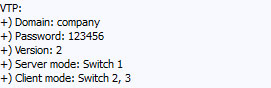
VTP:

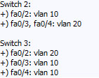
VLAN:
Port trên switch access:
Các bước thực hiện cấu hình bài lab này như sau:
Các cấu hình ban đầu cho thiết bị
Cấu hình VTP
Cấu hình VLAN
Cấu hình Inter-Vlan Routing
Cấu hình access-list để tùy chỉnh việc truy cập giữa các VLAN nếu cần thiết
Bước 1: Các cấu hình ban đầu cho thiết bị:
Thông thường trước khi cấu hình các bài lab, việc cấu hình các thông số cơ bản như hostname, password enable, cách mã hóa, password telnet, … cho thiết bị là điều rất cần thiết. Trong thực tế, việc cấu hình này sẽ ngăn chặn việc truy cập trái phép của người dùng truy cập vào thiết bị mạng:

Cấu hình này được thực hiện tương tự trên các thiết bị mạng còn lại
Bước 2: Cấu hình VTP:
Mục đích của VTP là để đồng bộ cơ sở dữ liệu về VLAN của hệ thống mạng. Giao thức này đặc biệt hữu ích khi chúng ta có mạng quy mô lớn. Việc thay đổi VLAN sẽ được thực hiện trên VTP mode server. Các thay đổi này sẽ được đồng bộ trên các thiết bị được cấu hình VTP mode client có cùng giá trị domain, password và version. Trong bài lab này, switch1 sẽ là mode server còn switch2, 3 sẽ là mode client:
 Việc cấu hình trên switch2 và switch3 hoàn toàn tương tự, chỉ thay giá trị “vtp mode server” bằng “vtp mode client”
Kiểm tra cấu hình vtp:

Để đồng bộ VLAN giữa các switch, đường kết nối giữa các switch phải được cấu hình trunk như sau:

Trong bài lab này, switch1 và switch2 kết nối với nhau thông qua kết nối giữa interface fa0/1 (switch1) và fa0/1 (switch1). Chính vì vậy interface fa0/1 của switch1 và interface fa0/1 của switch2 phải được cấu hình mode trunk. Tương tự với các interface khác.
Cũng cần phải lưu ý rằng, trong mô hình “router on a stick”, interface của switch kết nối với router phải được cấu hình mode trunk (fa0/24)
Bước 3: Cấu hình VLAN:
Vì VTP đã được cấu hình trên các switch, nên chúng ta chỉ thực hiện việc add VLAN trên switch1 (mode server). Thông tin về các VLAN sẽ được đồng bộ trên các switch còn lại:

Kiểm tra VLAN sau khi cấu hình:

Thông tin VLAN trên switch2, switch3 sau khi đồng bộ:

Cấu hình access port trên switch2 và switch3 để kết nối PC và server vào mạng:

Cấu hình native vlan cho mục đích quản lý:

Kiểm tra các port trunk:

Bước 4: Cấu hình Inter-Vlan Routing trên Router:

Lưu ý:
Các sub-interface phải được “encapsulation dot1Q” trước khi cấu hình địa chỉ IP. Nếu không thực hiện lệnh này, bạn cũng sẽ không thể cấu hình địa chỉ IP
“no shutdown” interface fa0/0 sau khi cấu hình cho các sub-interface
Bạn không phải “no shutdown” cho các sub-interface

Kiểm tra các interface và bảng định tuyến sau khi cấu hình trên router:

Cấu hình địa chỉ IP cho các PC và server để chuẩn bị thực hiện test mạng:

Thực hiện kiểm tra kết nối giữa các VLAN. Từ PC1 (192.168.10.10) lần lượt thực hiện ping tới các thiết bị trong cùng VLAN và khác VLAN với nó:


Như vậy là việc cấu hình Inter-Vlan Routing đã đúng.
Bước 5: Cấu hình access-list để tùy chỉnh việc truy cập giữa các VLAN nếu cần thiết
Giả sử bạn muốn giới hạn quyền truy cập của một số user từ VLAN này tới các VLAN khác. Khi đó bạn phải thực hiện cấu hình access-list để thực hiện điều này. Trong bài lab này, chúng ta sẽ thực hiện chặn lệnh ping được thực hiện từ PC1 (192.168.10.10) tới các server trong VLAN 20. Ta sẽ thực hiện tạo access-list 100 và add nó vào sub-interface fa0/0.10 như sau:

Lưu ý: mặc định access-list sẽ “deny all” khi không tìm được điều kiện nào phù hợp, chính vì vậy ta phải add điều kiện sau:

để các PC khác có thể ping được tới các server trong VLAN 20
Add access-list vào sub-interface fa0/0.10:

Kiểm tra kết quả:

Như vậy kết quả đúng như chúng ta mong đợi. PC1 không thế ping được tới các thiết bị của VLAN 2 trong khi đó các PC khác vẫn có thể ping được bình thường
Trong bài tiết theo mình sẽ trình bày cách cấu hình Inter-Vlan Routing trên thiết bị switch lớp 3
Video clip cấu hình chi tiết: http://www.mediafire.com/download.php?d9g51tk5uz76xsm
Lab packet tracer: http://www.mediafire.com/download.php?7xkwk3ci7uv2tka
Vấn đề ở đây là làm thế nào có thể từ một trong những người sử dụng VLAN ( thuộc về 1 broadcast domain), sử dụng được các dịch vụ được cung cấp bởi một VLAN khác? Do vậy giải pháp định tuyến trên VLAN đã được đề cập đến.
Có nhiều phương pháp định tuyến, nhưng trong phạm vi bài Lab này chúng ta chỉ đề cập đến phương pháp định tuyến giữa các VLAN sử dụng Router ngoài. Tuy nhiên phương pháp định tuyến giữa các VLAN tốt nhất sử dụng Switch Layer 3 sẽ được đề cập trong chương trình CCNP.
Phương pháp này được thiết lập có hiệu quả nhất bằng cách cung cấp một liên kết trunk duy nhất giữa Switch và Router mà có thể mang lưu lượng truy cập của nhiều VLAN và trong đó các lưu lượng ấy lần lượt có thể được định tuyến bởi Router.

Phương pháp này được thiết lập có hiệu quả nhất bằng cách cung cấp một liên kết trunk duy nhất giữa Switch và Router mà có thể mang lưu lượng truy cập của nhiều VLAN và trong đó các lưu lượng ấy lần lượt có thể được định tuyến bởi Router.
Với Inter-VLAN Routing, Router nhận frame từ Switch với gói tin xuất phát từ một VLAN đã được tag. Nó liên kết các frame với các subinterface thích hợp và sau đó giải mã nội dung của frame (phần IP packet). Router sau đó thực hiện chức năng của Layer 3 dựa trên địa chỉ mạng đích có trong gói tin IP để xác định subinterface cần chuyển tiếp gói IP. Các IP packet bây giờ được đóng gói thành frame theo chuẩn dot1Q (hoặc ISL) để nhận dạng VLAN của subinterface chuyển tiếp và truyền đi trên đường trunk vào Switch.
Cấu hình Inter-Vlan Routing sử dụng router
Sau khi chia hạ tầng mạng ra thành nhiều VLAN. Trong đó mỗi VLAN là một broadcast domain, chỉ các thiết bị trong cùng một VLAN mới có thể truyền thông được với nhau. Về nguyên lý chúng ta hoàn toàn có thể kết nối các VLAN bằng cách sử dụng một thiết bị lớp 3 làm vai trò định tuyến. Thiết bị lớp 3 này có thể là router và switch layer 3. Trong bài này mình sẽ giới thiệu tới các bạn bài lab cấu hình Inter-Vlan Routing sử dụng router theo phương thức “Router on a stick”. Sơ đồ lab như sau:
Một số yêu cầu của bài lab:
VTP:


VLAN:
Port trên switch access:

Các bước thực hiện cấu hình bài lab này như sau:
Các cấu hình ban đầu cho thiết bị
Cấu hình VTP
Cấu hình VLAN
Cấu hình Inter-Vlan Routing
Cấu hình access-list để tùy chỉnh việc truy cập giữa các VLAN nếu cần thiết
Bước 1: Các cấu hình ban đầu cho thiết bị:
Thông thường trước khi cấu hình các bài lab, việc cấu hình các thông số cơ bản như hostname, password enable, cách mã hóa, password telnet, … cho thiết bị là điều rất cần thiết. Trong thực tế, việc cấu hình này sẽ ngăn chặn việc truy cập trái phép của người dùng truy cập vào thiết bị mạng:
Cấu hình này được thực hiện tương tự trên các thiết bị mạng còn lại
Bước 2: Cấu hình VTP:
Mục đích của VTP là để đồng bộ cơ sở dữ liệu về VLAN của hệ thống mạng. Giao thức này đặc biệt hữu ích khi chúng ta có mạng quy mô lớn. Việc thay đổi VLAN sẽ được thực hiện trên VTP mode server. Các thay đổi này sẽ được đồng bộ trên các thiết bị được cấu hình VTP mode client có cùng giá trị domain, password và version. Trong bài lab này, switch1 sẽ là mode server còn switch2, 3 sẽ là mode client:
Việc cấu hình trên switch2 và switch3 hoàn toàn tương tự, chỉ thay giá trị “vtp mode server” bằng “vtp mode client”Kiểm tra cấu hình vtp:
Để đồng bộ VLAN giữa các switch, đường kết nối giữa các switch phải được cấu hình trunk như sau:
Trong bài lab này, switch1 và switch2 kết nối với nhau thông qua kết nối giữa interface fa0/1 (switch1) và fa0/1 (switch1). Chính vì vậy interface fa0/1 của switch1 và interface fa0/1 của switch2 phải được cấu hình mode trunk. Tương tự với các interface khác.
Cũng cần phải lưu ý rằng, trong mô hình “router on a stick”, interface của switch kết nối với router phải được cấu hình mode trunk (fa0/24)
Bước 3: Cấu hình VLAN:
Vì VTP đã được cấu hình trên các switch, nên chúng ta chỉ thực hiện việc add VLAN trên switch1 (mode server). Thông tin về các VLAN sẽ được đồng bộ trên các switch còn lại:
Kiểm tra VLAN sau khi cấu hình:
Thông tin VLAN trên switch2, switch3 sau khi đồng bộ:
Cấu hình access port trên switch2 và switch3 để kết nối PC và server vào mạng:
Cấu hình native vlan cho mục đích quản lý:
Kiểm tra các port trunk:
Bước 4: Cấu hình Inter-Vlan Routing trên Router:
Lưu ý:
Các sub-interface phải được “encapsulation dot1Q” trước khi cấu hình địa chỉ IP. Nếu không thực hiện lệnh này, bạn cũng sẽ không thể cấu hình địa chỉ IP
“no shutdown” interface fa0/0 sau khi cấu hình cho các sub-interface
Bạn không phải “no shutdown” cho các sub-interface
Kiểm tra các interface và bảng định tuyến sau khi cấu hình trên router:
Cấu hình địa chỉ IP cho các PC và server để chuẩn bị thực hiện test mạng:
Thực hiện kiểm tra kết nối giữa các VLAN. Từ PC1 (192.168.10.10) lần lượt thực hiện ping tới các thiết bị trong cùng VLAN và khác VLAN với nó:
Như vậy là việc cấu hình Inter-Vlan Routing đã đúng.
Bước 5: Cấu hình access-list để tùy chỉnh việc truy cập giữa các VLAN nếu cần thiết
Giả sử bạn muốn giới hạn quyền truy cập của một số user từ VLAN này tới các VLAN khác. Khi đó bạn phải thực hiện cấu hình access-list để thực hiện điều này. Trong bài lab này, chúng ta sẽ thực hiện chặn lệnh ping được thực hiện từ PC1 (192.168.10.10) tới các server trong VLAN 20. Ta sẽ thực hiện tạo access-list 100 và add nó vào sub-interface fa0/0.10 như sau:
Lưu ý: mặc định access-list sẽ “deny all” khi không tìm được điều kiện nào phù hợp, chính vì vậy ta phải add điều kiện sau:
để các PC khác có thể ping được tới các server trong VLAN 20
Add access-list vào sub-interface fa0/0.10:
Kiểm tra kết quả:
Như vậy kết quả đúng như chúng ta mong đợi. PC1 không thế ping được tới các thiết bị của VLAN 2 trong khi đó các PC khác vẫn có thể ping được bình thường
Trong bài tiết theo mình sẽ trình bày cách cấu hình Inter-Vlan Routing trên thiết bị switch lớp 3
Video clip cấu hình chi tiết: http://www.mediafire.com/download.php?d9g51tk5uz76xsm
Lab packet tracer: http://www.mediafire.com/download.php?7xkwk3ci7uv2tka
Inter-VLAN Routing
Networks are constantly evolving, and in the past few years a number of trends have become apparent. First of all, the Internet Protocol (IP) has become the Layer 3 protocol of choice for modern networks, with other Layer 3 protocols such as Internetwork Packet Exchange (IPX) and AppleTalk rapidly being phased out. IP interconnects the Internet. The increasing reliance of organizations on the Internet has promoted IP as the Layer 3 protocol of choice. Secondly, local-area networks (LANs) have seen tremendous advances in terms of performance, bandwidth, and lowering cost. The LAN provides the medium over which users and devices connect to the internal IP network and the Internet hence is an important component of networking. LAN topologies have evolved from traditionally being single, flat broadcast domains into multi-virtual LAN (VLAN) topologies, with inter-VLAN routing required to enable communications between each VLAN. Multiple VLANs increase network efficiency by reducing broadcast domain size, as well as providing a mechanism to allow network layer access control to be applied between VLANs. Using multiple VLANs also means that the resiliency of the network relies less on Layer 2 protocols such as Spanning Tree Protocol (STP), and more upon Layer 3 routing protocols. Modern Layer 3 routing protocols are much more intelligent than STP and as a result can converge much more quickly in the event of a network failure. Finally, segmenting a LAN network into VLANs allows for the isolation of problems to a smaller segment of network, allowed for reduced impact on the network and easier fault finding.
All of the above factors have caused the requirements for inter-VLAN routing within LAN networks to soar over the past few years. Even though this book is primarily about switches, which are traditionally Layer 2-only devices, it is important to understand the basics of inter-VLAN routing. Possessing this knowledge helps you to understand Layer 3 switches, which are becoming cost-effective, high performance alternatives to traditional routers for routing IP traffic between LAN segments. Possessing a fundamental understanding of inter-VLAN is important if you are to design multilayer topologies that are stable, available, and scaleable.
This chapter introduces you to the basic inter-VLAN routing architectures, using both traditional Cisco routers and basic Cisco Layer 3 switching. You also learn about multilayer LAN topologies and how a hierarchical design allows for scalability and a redundant topology that in the event of failure converges quickly and efficiently with minimal disruption to the network.
The following scenarios are presented in this chapter:
Within a LAN topology, inter-VLAN routing is used to route packets between different VLANs. Three common inter-VLAN routing architectures are used in modern LAN networks today:
This section examines each of these in detail, outlining any restrictions or issues associated with each.
The router-on–a-stick architecture is the most basic method of inter-VLAN routing. In this architecture, a router is simply connected to each VLAN and forwards inter-VLAN traffic between the appropriate VLANs. Figure 5-1 shows this architecture.
As you can see in Figure 5-1, the router has a physical Ethernet interface dedicated for each VLAN. If IP hosts on VLAN 100 need to communicate with hosts of VLAN 200, IP packets with the appropriate source and destination IP addresses are sent to the router, which looks up the destination IP address and forwards to the appropriate host on the destination VLAN. The router-on-a-stick architecture is simple to understand because the Layer 2 functions (provided by a switch) and Layer 3 functions (provided by a router) are physically separated.
The major issue with this architecture is performance. Because routers are software-based, they cannot route packets as fast as switches (hardware-based) can switch frames. Even if you are using high-performance routers, the physical interface connecting each VLAN to the router is a bottleneck because it can transmit packets only at 10 Mbps, 100 Mbps, or 1 Gbps depending on the interface type. This restriction means that the router becomes a performance bottleneck when routing between high-speed VLANs.
Another issue with this architecture is the number of routers and physical interfaces required to support multiple VLANs. A dedicated Ethernet interface is required per VLAN. Routers are low-density devices, meaning that there is a high cost per port and multiple routing devices might be required to support multiple VLANs, increasing the complexity of the network.
Finally, all inter-VLAN traffic must travel via the router. In Figure 5-1, even though the PCs in VLAN 100 and VLAN 200 are connected to the same switch, all inter-VLAN traffic between the PCs must be sent through the router, which is inefficient.
As discussed in the last section, the router-on-a-stick architecture has physical limitations based upon a dedicated physical interface being required for each VLAN. This limitation can be removed by using trunk interfaces, where multiple VLANs are supported on a single physical interface by using tagging technologies such as 802.1Q or ISL. Rather than using physical interfaces to attach the router to each VLAN, virtual or logical interfaces are used to attach the router to each VLAN. Figure 5-2shows this architecture.
In Figure 5-2, virtual interfaces (rather than physical interfaces) are used to connect the router to each VLAN. A single physical trunk interface transports tagged VLAN traffic to the router, with the tag determining to which virtual interface a frame should be forwarded for routing. Apart from the differences between using physical interfaces per VLAN as opposed to virtual interfaces per VLAN, this architecture is essentially identical to the traditional router-on-a-stick architecture and suffers the same performance limitations, because the routing engine is still software-based and the trunk interface is limited to 10 Mbps, 100 Mbps, or 1 Gbps.
The architectures discussed thus far represent the traditional inter-VLAN routing architectures. The major issue with these architectures is performance—if gigabit speed routing is required between VLANs, extremely high performance and costly routers are required. A new form of inter-VLAN routing on the LAN has emerged in recent years called Layer 3 switching. With a Layer 3 switch, the traditionally separated Layer 2 and Layer 3 functions are combined into a single device, eliminating the bottleneck associated with the cable between a router and switch by replacing the cable with a high-speed backplane connection. Layer 3 switches also typically perform routing in specially designed hardware circuitry rather than software, using specialized hardware that can perform routing functions at high speed. This means that the performance of Layer 3 switches is much higher than traditional router-on-a-stick architectures. For example, if you use a Cisco 3640 series router in the router-on-a-stick architecture, you can achieve routing speeds of up to 40,000 packets per second. If you compare this with a Cisco Catalyst 3550-24-EMI Layer 3 switch, which is actually cheaper than a Cisco 3640 router, you can route packets at up to 6.6 million packets per second. This is obviously quite a difference and highlights the limitations of using router-on-a-stick architectures for inter-VLAN routing on the LAN. Of course, the Cisco 3640 router still has a place in the network; it supports a wide variety of diverse media, including serial and ATM connections for WAN connectivity; also supports advanced features such as firewalling, encryption, and so on—all of which are not supported on Cisco Catalyst switches.
The Layer 3 switch uses application-specific integrated circuits (ASICs), which are hardware chips that can route traffic at very high speeds. These ASICs are installed on the switching engine of a Layer 3 switch, which traditionally switches frames at Layer 2. The ASICs allow the switching engine to also switch frames that contain packets sent between different VLANs. Each ASIC is programmed with the information required to route traffic from one VLAN to another, without having to pass the traffic through the CPU of the routing engine. This information includes the egress port, egress VLAN, and new destination MAC address that should be written for the frame that is sent. Some form of route cache is normally used to store such information, with the ASIC searching the cache for routing information for the destination IP address of packets as they are received. How this information is programmed into the route cache depends on the Layer 3 switch architecture used; however, the end result is essentially the same.
In addition to the high-speed routing feature, these ASICs also can apply security access control list (ACL) filtering and Layer 3 quality of service (QoS) classification, all at wire-speed, meaning these useful features can be turned on without affecting performance.
NOTE
The internal mechanics of Layer 3 switching are covered in more detail in Chapter 6, "Layer 3 Switching."
When examining the architecture of a Layer 3 switch, it is important to understand that several different approaches to Layer 3 switching implemented by Cisco exist:
In this chapter, you learn how to configure the Catalyst 4000 using the Layer 3 routing module in a router-on-a-stick architecture. You also learn how to configure Layer 3 switching on the Catalyst 3550, which is based upon a CEF architecture. In Chapter 6, you learn about MLS and CEF on the Catalyst 6000/6500 family of switches.
All of the above factors have caused the requirements for inter-VLAN routing within LAN networks to soar over the past few years. Even though this book is primarily about switches, which are traditionally Layer 2-only devices, it is important to understand the basics of inter-VLAN routing. Possessing this knowledge helps you to understand Layer 3 switches, which are becoming cost-effective, high performance alternatives to traditional routers for routing IP traffic between LAN segments. Possessing a fundamental understanding of inter-VLAN is important if you are to design multilayer topologies that are stable, available, and scaleable.
This chapter introduces you to the basic inter-VLAN routing architectures, using both traditional Cisco routers and basic Cisco Layer 3 switching. You also learn about multilayer LAN topologies and how a hierarchical design allows for scalability and a redundant topology that in the event of failure converges quickly and efficiently with minimal disruption to the network.
The following scenarios are presented in this chapter:
- Scenario 5-1: Configuring Basic IP Routing
- Scenario 5-2: Configuring Layer 3 Switching
- Scenario 5-3: Implementing a Redundant Multilayer Topology
Inter-VLAN Routing Architectures
Within a LAN topology, inter-VLAN routing is used to route packets between different VLANs. Three common inter-VLAN routing architectures are used in modern LAN networks today:
- Router-on-a-stick
- Router-on-a-stick using trunks
- Layer 3 switching
This section examines each of these in detail, outlining any restrictions or issues associated with each.
Router-on-a-Stick
The router-on–a-stick architecture is the most basic method of inter-VLAN routing. In this architecture, a router is simply connected to each VLAN and forwards inter-VLAN traffic between the appropriate VLANs. Figure 5-1 shows this architecture.

As you can see in Figure 5-1, the router has a physical Ethernet interface dedicated for each VLAN. If IP hosts on VLAN 100 need to communicate with hosts of VLAN 200, IP packets with the appropriate source and destination IP addresses are sent to the router, which looks up the destination IP address and forwards to the appropriate host on the destination VLAN. The router-on-a-stick architecture is simple to understand because the Layer 2 functions (provided by a switch) and Layer 3 functions (provided by a router) are physically separated.
The major issue with this architecture is performance. Because routers are software-based, they cannot route packets as fast as switches (hardware-based) can switch frames. Even if you are using high-performance routers, the physical interface connecting each VLAN to the router is a bottleneck because it can transmit packets only at 10 Mbps, 100 Mbps, or 1 Gbps depending on the interface type. This restriction means that the router becomes a performance bottleneck when routing between high-speed VLANs.
Another issue with this architecture is the number of routers and physical interfaces required to support multiple VLANs. A dedicated Ethernet interface is required per VLAN. Routers are low-density devices, meaning that there is a high cost per port and multiple routing devices might be required to support multiple VLANs, increasing the complexity of the network.
Finally, all inter-VLAN traffic must travel via the router. In Figure 5-1, even though the PCs in VLAN 100 and VLAN 200 are connected to the same switch, all inter-VLAN traffic between the PCs must be sent through the router, which is inefficient.
Router-on-a-Stick Using Trunks
As discussed in the last section, the router-on-a-stick architecture has physical limitations based upon a dedicated physical interface being required for each VLAN. This limitation can be removed by using trunk interfaces, where multiple VLANs are supported on a single physical interface by using tagging technologies such as 802.1Q or ISL. Rather than using physical interfaces to attach the router to each VLAN, virtual or logical interfaces are used to attach the router to each VLAN. Figure 5-2shows this architecture.

In Figure 5-2, virtual interfaces (rather than physical interfaces) are used to connect the router to each VLAN. A single physical trunk interface transports tagged VLAN traffic to the router, with the tag determining to which virtual interface a frame should be forwarded for routing. Apart from the differences between using physical interfaces per VLAN as opposed to virtual interfaces per VLAN, this architecture is essentially identical to the traditional router-on-a-stick architecture and suffers the same performance limitations, because the routing engine is still software-based and the trunk interface is limited to 10 Mbps, 100 Mbps, or 1 Gbps.
Routing Using Layer 3 Switches
The architectures discussed thus far represent the traditional inter-VLAN routing architectures. The major issue with these architectures is performance—if gigabit speed routing is required between VLANs, extremely high performance and costly routers are required. A new form of inter-VLAN routing on the LAN has emerged in recent years called Layer 3 switching. With a Layer 3 switch, the traditionally separated Layer 2 and Layer 3 functions are combined into a single device, eliminating the bottleneck associated with the cable between a router and switch by replacing the cable with a high-speed backplane connection. Layer 3 switches also typically perform routing in specially designed hardware circuitry rather than software, using specialized hardware that can perform routing functions at high speed. This means that the performance of Layer 3 switches is much higher than traditional router-on-a-stick architectures. For example, if you use a Cisco 3640 series router in the router-on-a-stick architecture, you can achieve routing speeds of up to 40,000 packets per second. If you compare this with a Cisco Catalyst 3550-24-EMI Layer 3 switch, which is actually cheaper than a Cisco 3640 router, you can route packets at up to 6.6 million packets per second. This is obviously quite a difference and highlights the limitations of using router-on-a-stick architectures for inter-VLAN routing on the LAN. Of course, the Cisco 3640 router still has a place in the network; it supports a wide variety of diverse media, including serial and ATM connections for WAN connectivity; also supports advanced features such as firewalling, encryption, and so on—all of which are not supported on Cisco Catalyst switches.
The Layer 3 switch uses application-specific integrated circuits (ASICs), which are hardware chips that can route traffic at very high speeds. These ASICs are installed on the switching engine of a Layer 3 switch, which traditionally switches frames at Layer 2. The ASICs allow the switching engine to also switch frames that contain packets sent between different VLANs. Each ASIC is programmed with the information required to route traffic from one VLAN to another, without having to pass the traffic through the CPU of the routing engine. This information includes the egress port, egress VLAN, and new destination MAC address that should be written for the frame that is sent. Some form of route cache is normally used to store such information, with the ASIC searching the cache for routing information for the destination IP address of packets as they are received. How this information is programmed into the route cache depends on the Layer 3 switch architecture used; however, the end result is essentially the same.
In addition to the high-speed routing feature, these ASICs also can apply security access control list (ACL) filtering and Layer 3 quality of service (QoS) classification, all at wire-speed, meaning these useful features can be turned on without affecting performance.
NOTE
The internal mechanics of Layer 3 switching are covered in more detail in Chapter 6, "Layer 3 Switching."
When examining the architecture of a Layer 3 switch, it is important to understand that several different approaches to Layer 3 switching implemented by Cisco exist:
- Router-on-a-stick— Some chassis-based Catalyst switches (e.g., the Catalyst 4000 and 5000) support routing modules, which are effectively routers on a blade. Apart from having a high-speed connection to the switch backplane, the routing module is essentially a router-on-a-stick, with all routed traffic requiring processing through the routing module. This architecture is not really Layer 3 switching at all because the switch hardware has no special ASICs for Layer 3 switching; instead, it is a high-speed, router-on-a-stick architecture.
- Multilayer switching (MLS)— In this architecture, hardware-based ASICs on the switching component of the Layer 3 switch refer to a cache that is populated with the required information to route a packet received on one VLAN to another VLAN, without having to pass the packet through the routing engine. With MLS, the Layer 3 switching cache is populated after the first packet of a particular flow (connection) is received and the route processor is queried for routing information.
- Cisco Express Forwarding (CEF)— This architecture is identical to MLS in terms of the hardware-based ASICs referring to a Layer 3 cache for information as to how to route packets between VLANs without involving the router processor. CEF differs from MLS in terms of the way the Layer 3 cache is populated. CEF pre-populates the caches with full routing information, which means the route processor never needs to be queried for the initial routing information that is required in a MLS architecture.
In this chapter, you learn how to configure the Catalyst 4000 using the Layer 3 routing module in a router-on-a-stick architecture. You also learn how to configure Layer 3 switching on the Catalyst 3550, which is based upon a CEF architecture. In Chapter 6, you learn about MLS and CEF on the Catalyst 6000/6500 family of switches.
Đăng nhận xét